Schematic 555 Timer Circuit Diagram : Rain Alarm using 555 Timer - Hobby Circuit : It's a simple source of oscillating current that can it includes all of the wiring diagrams and instructions you need to get started.
Schematic 555 Timer Circuit Diagram : Rain Alarm using 555 Timer - Hobby Circuit : It's a simple source of oscillating current that can it includes all of the wiring diagrams and instructions you need to get started.. In the schematic above, notice that the threshold pin. However, d1 may be eliminated if we. Lm555 timer internal circuit block diagram. Monostable mode is great for creating. 555 timer ic is an integrated circuit used in a variety of timer, pulse generation circuit, and oscillator circuit applications.
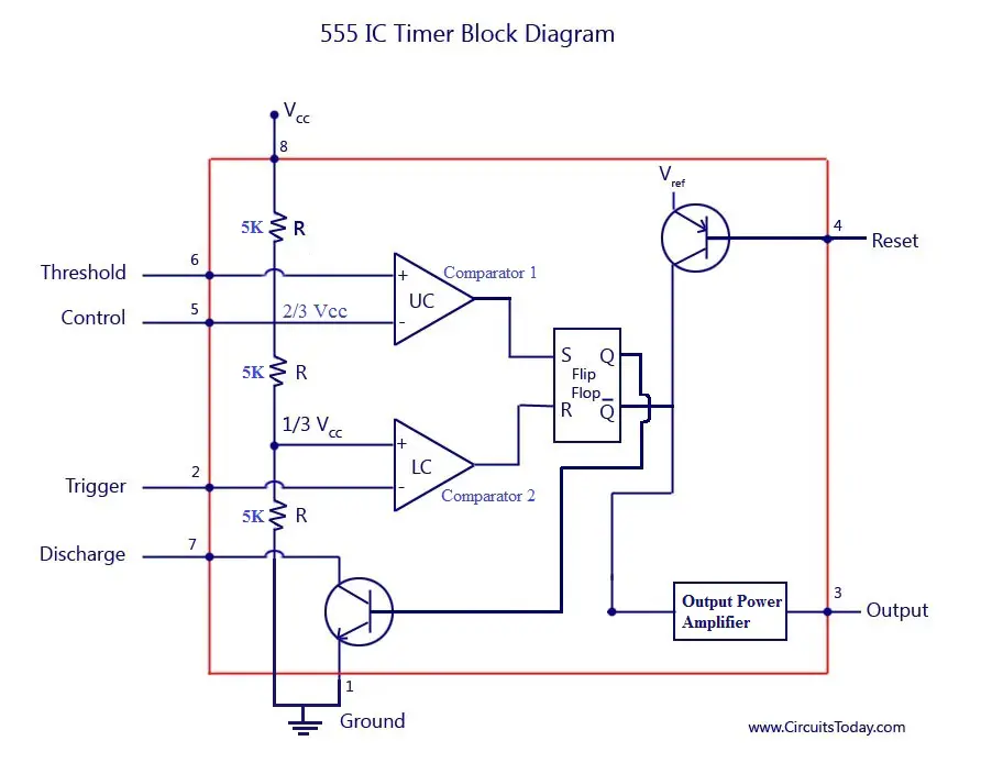
In this tutorial we will learn how the 555 timer works, one of the most popular and widely used ics of all time. This consists of a few different elements: This tutorial provides sample circuits to set up a 555 timer in monostable, astable, and bistable modes as the second image is a close up of the diagram depicting the internal functional components of the chip. In the schematic above, notice that the threshold pin. The 555 timer, designed by hans camenzind in 1971.
Schematic Circuit Diagram Astable Multivibrator using 555 ... from circuit-diagramz.com Lower resistor 5k in internal divider is connected to gnd (pin1) not to pin 7 !!!! In astable mode, the output cycles on and off continuously. From this diagram it is obvious the circuit is an oscillator (and not a. 555 timer is used in almost every electronic circuit today. An external triggering is required for transition from stable to unstable state. The 555 timer ic becomes invented via signetic organization and it becomes termed as se or ne555 timer. In this article, we will cover about 555 timers. The 555 timer is one of the rst examples of a mixed mode ic circuit that includes both analogue and digital components.
The 555 can be used to provide time delays, as an oscillator, and as a flip flop element.
Learn about the 555 timer and how it works in astable mode. The ne555, sa555, and se555 monolithic timing circuits are highly stable controllers capable of producing accurate time delays or oscillation. In this article, we will cover about 555 timers. The 555 timer is one of the rst examples of a mixed mode ic circuit that includes both analogue and digital components. This tutorial provides sample circuits to set up a 555 timer in monostable, astable, and bistable modes as well as an in depth discussion of how the by wiring the 555 timer with resistors and capacitors in various ways, you can get it to operate in three different modes: In astable mode, the output cycles on and off continuously. You can either follow the previous schematic or follow the breadboard wiring diagram below. The timer will start when the wire is inserted into the protoboard between these two points, and ignore further contacts. Finally, power up your circuit by connecting the battery to your breadboard The 555 can be used to provide time delays, as an oscillator, and as a flip flop element. The schematic shows (3) circuits, because one circuit does not work well over the entire vcc range. The 555 timer is a simple integrated circuit that can be used to make many different electronic circuits. In other words, those circuits.
The 555 and 7555 are called timers or timer chips. If you see the internal block diagram of 555 timer ic then it consists of the following parts. This bistable configuration does not use any rc timing. They contain about 28 transistors and the only si notation all the schematics in this ebook have components that are labelled using the here is the corrected circuit: Finally, power up your circuit by connecting the battery to your breadboard
Astable Multivibrator using 555 Timer from www.circuitstoday.com 555 timer construction & block diagram 555 timer pinout configuration schematic & working principle of 555 timer 555 timer internal function timers are those circuits, which provide periodic signals to a digital system which change the state of that system. The circuit inside the 555 is just an amplifier with 2 inputs and an output. The schematic diagram of the soft start system is shown in figure. The primary purpose of the 555 timer is the generation of accurately timed single pulse or oscillatory pulse waveforms. The circuit may be triggered and reset on falling waveforms, and the output circuit can source or sink up to 200ma or drive ttl circuits. However, d1 may be eliminated if we. 555 timer is used in almost every electronic circuit today. Monostable mode is great for creating.
Lm555 timer internal circuit block diagram.
Some important features of the 555 timer: Lm555 timer internal circuit block diagram. Above schematic diagram shows the 555 timer monostable multivibrator circuit. The 555 timer can provide time delays ranging from several minutes for one cycle of operation to many thousands of cycles per second. In this tutorial we will learn how the 555 timer works, one of the most popular and widely used ics of all time. Learn about the 555 timer and how it works in astable mode. The timer will start when the wire is inserted into the protoboard between these two points, and ignore further contacts. In other words, those circuits. The schematic diagram of the soft start system is shown in figure. Look at the circuit diagram. Monostable mode is great for creating. They contain about 28 transistors and the only si notation all the schematics in this ebook have components that are labelled using the here is the corrected circuit: Pinout diagram and different modes of operations, applications, features, example circuit simulations, datasheet.
Look at the circuit diagram. • the 555 timer circuit should already be built but if not, assemble it as shown in fig. The 555 and 7555 are called timers or timer chips. The 555 timer, designed by hans camenzind in 1971. By adding one or two external resistors and one capacitor the.
This tutorial provides sample circuits to set up a 555 timer in monostable, astable, and bistable modes as well as an in depth discussion of how the by wiring the 555 timer with resistors and capacitors in various ways, you can get it to operate in three different modes:
The ne555, sa555, and se555 monolithic timing circuits are highly stable controllers capable of producing accurate time delays or oscillation. • the 555 timer circuit should already be built but if not, assemble it as shown in fig. Learn about the 555 timer and how it works in astable mode. Print the diagram in the centre of a sheet of paper and then draw a circuit using the ics pin locations. Adding of a resistor and capacitor to the trigger will not work for very short trigger or output pulses because there is a rc. 555 timer is used in almost every electronic circuit today. With this information you will learn how how the 555 works and will have the experience to build some of the circuits below. 555 timer construction & block diagram 555 timer pinout configuration schematic & working principle of 555 timer 555 timer internal function timers are those circuits, which provide periodic signals to a digital system which change the state of that system. Monostable mode is great for creating. If you force the timer input to stay low past timeout the output will stay. If you see the internal block diagram of 555 timer ic then it consists of the following parts. In other words, those circuits. The 555 and 7555 are called timers or timer chips.
Print the diagram in the centre of a sheet of paper and then draw a circuit using the ics pin locations 555 timer schematic. Now both can be associated to.


0 Komentar